Posted at November 6, 2014 @ 2:29 am by marknet
One of the special projects that we’ve done at Owen Machine was to design and build a custom tripod mount for a Japanese aerial machine gun camera. The camera was originally used to train the rear gunner on Japanese World War 2 dive bombers and was taken as a souvenir at the end of the war.
Careful measurements were taken of the camera mounts fixed to the bottom of the camera paying close attention to the bushing diameters and the center to center distance between them. The camera mount and tripod body were then drawn on CAD.
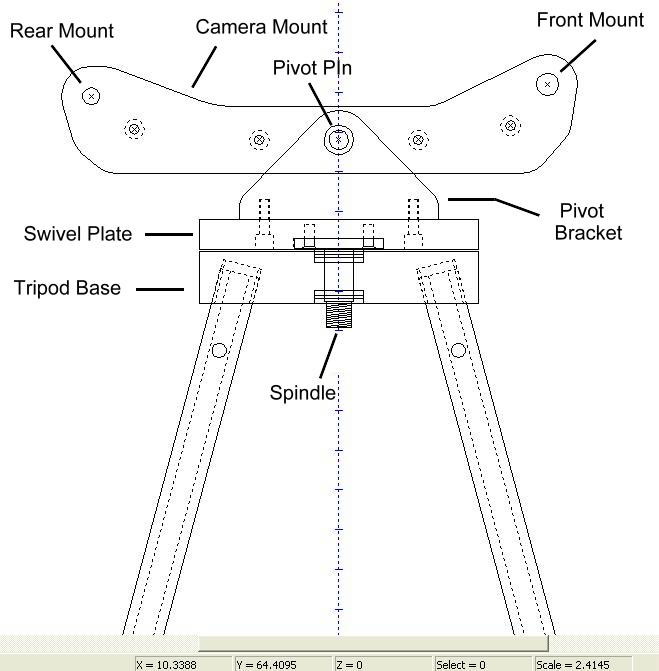
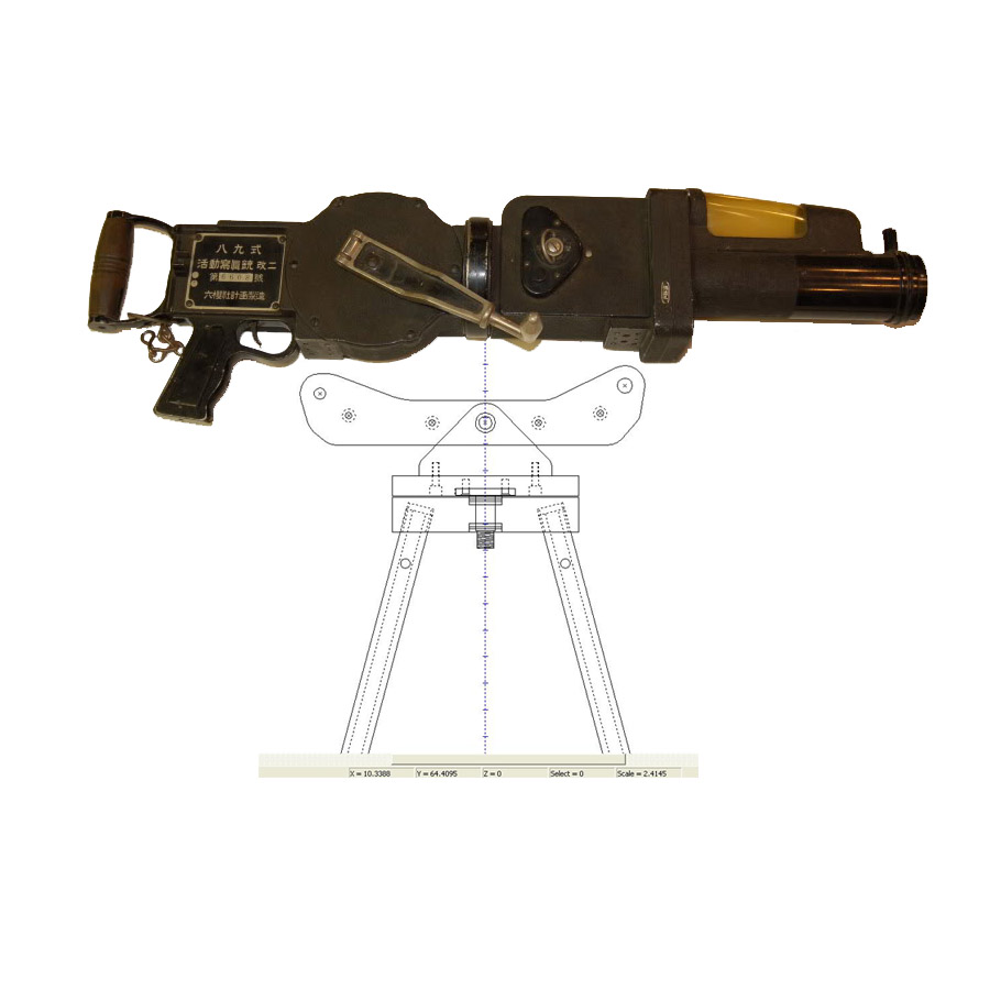
This image shows a picture of the machine gun camera transposed on the tripod drawing to show the relative scale.
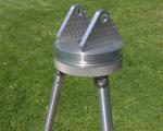
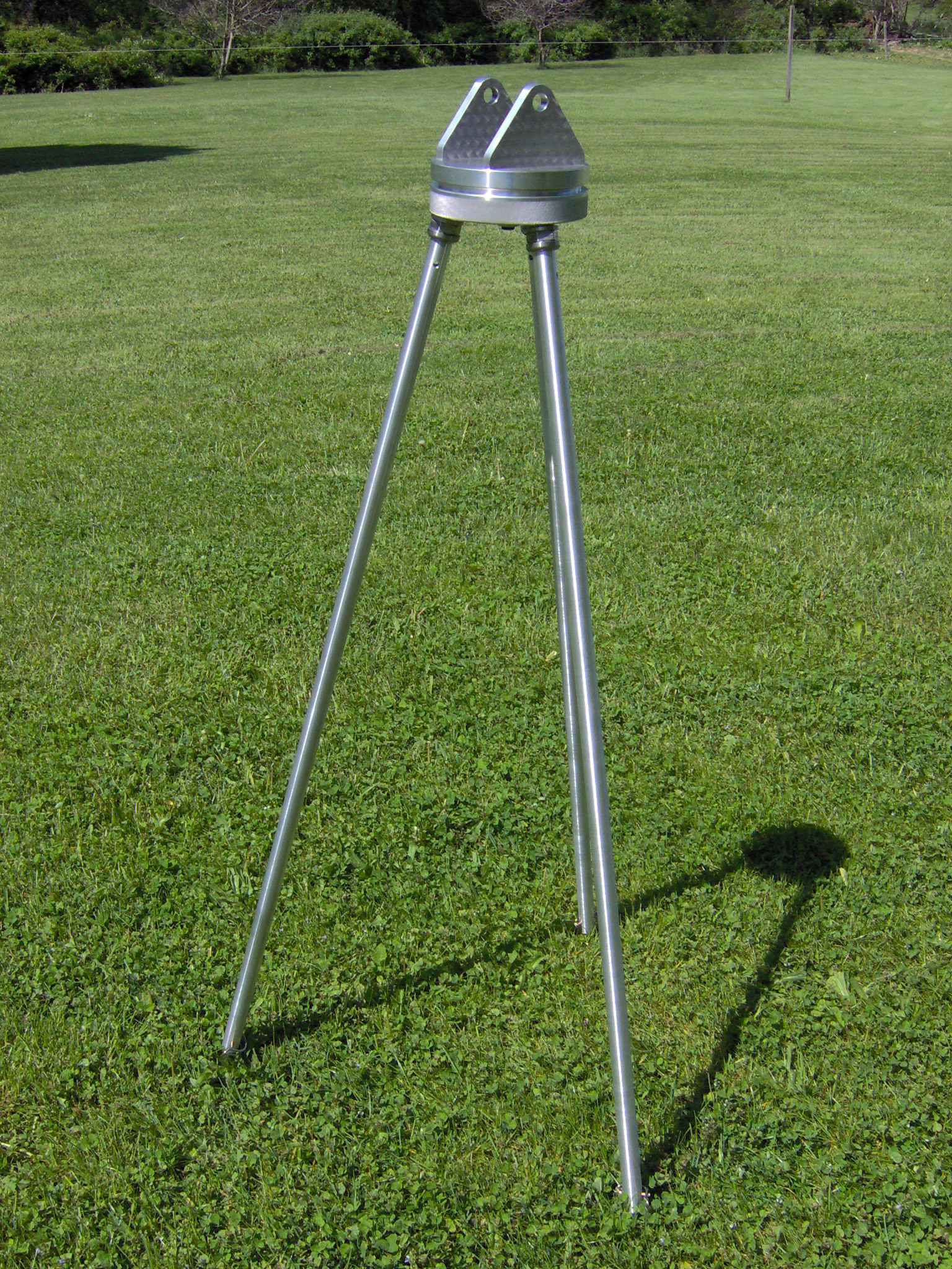
The completed tripod is shown below. The overall height is approximately 4′ 6″ with the leg extensions fully retracted. Extending the legs will raise the tripod another 12 inches.
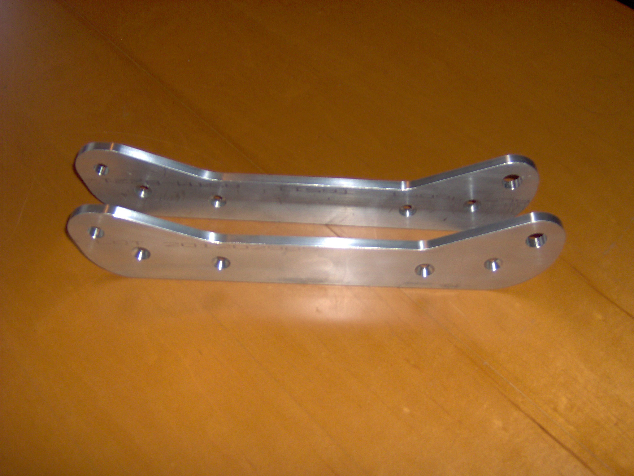
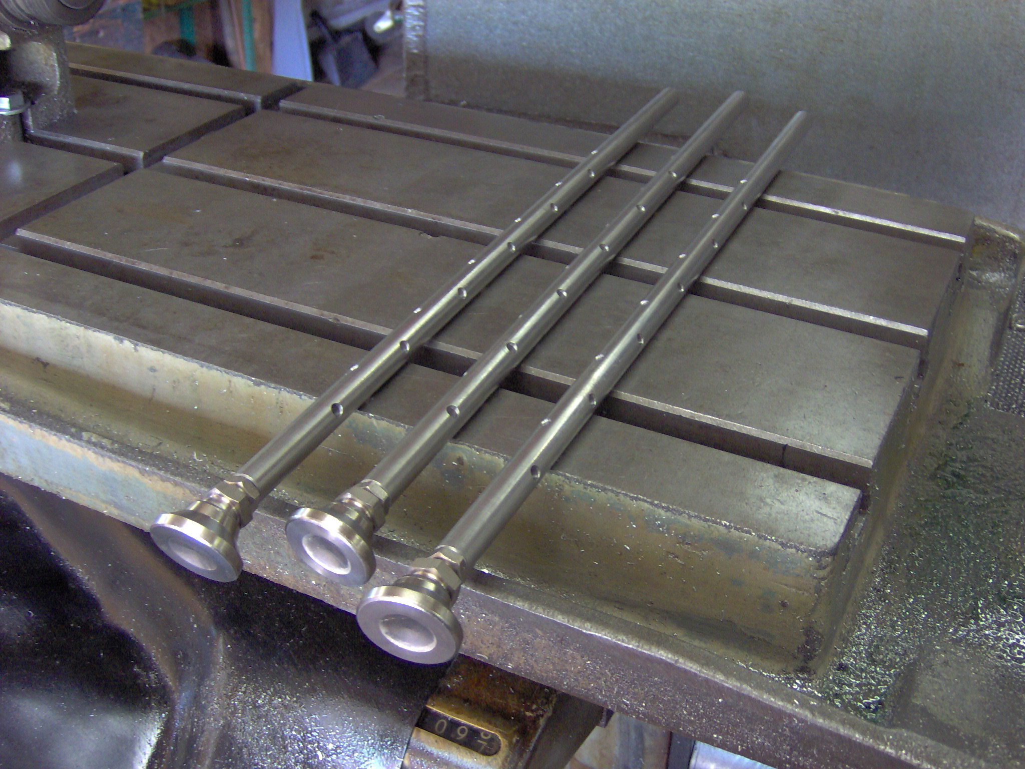
The camera mounting rails were machined first and is comprised of a left hand and right hand bracket.
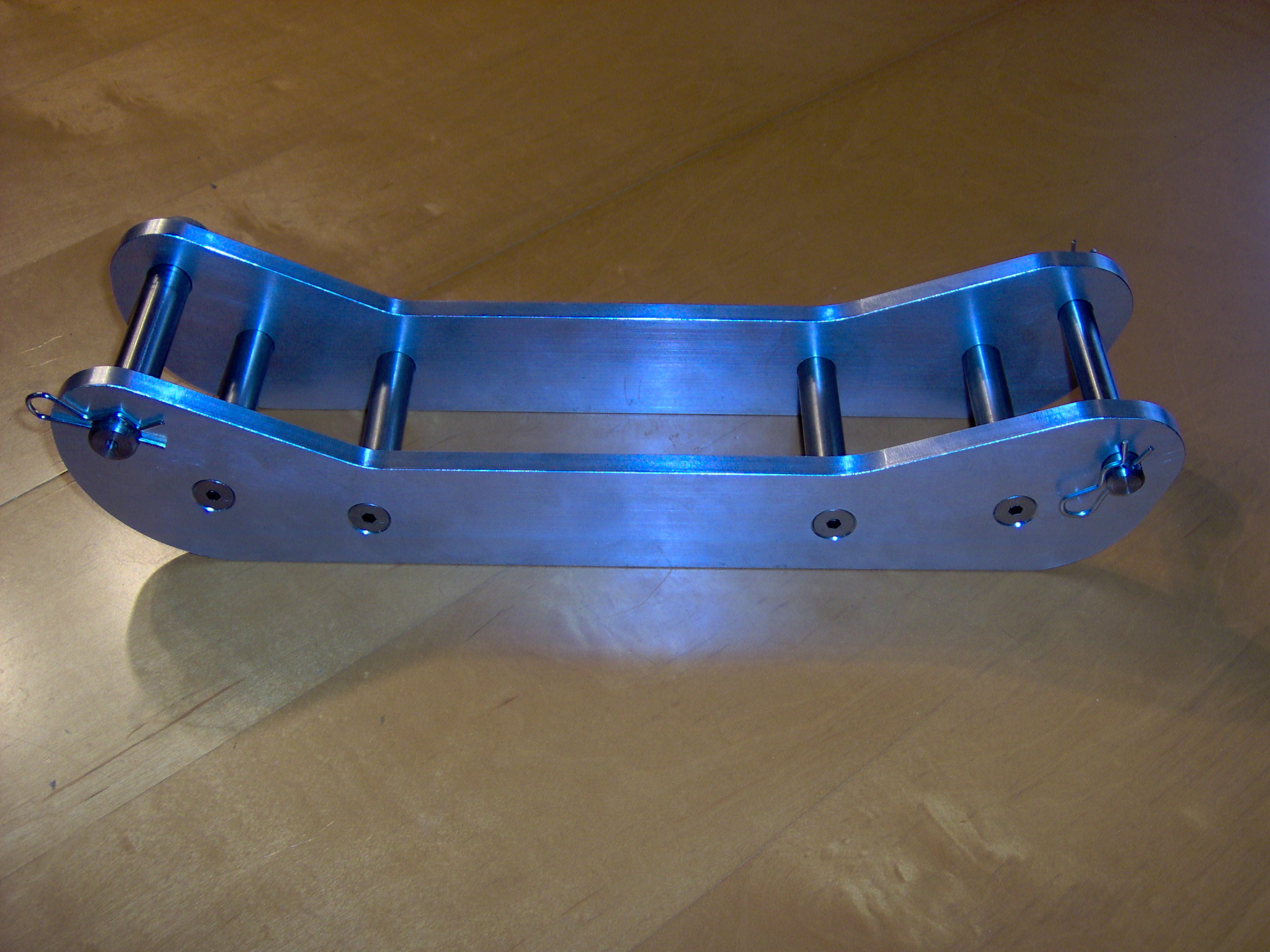
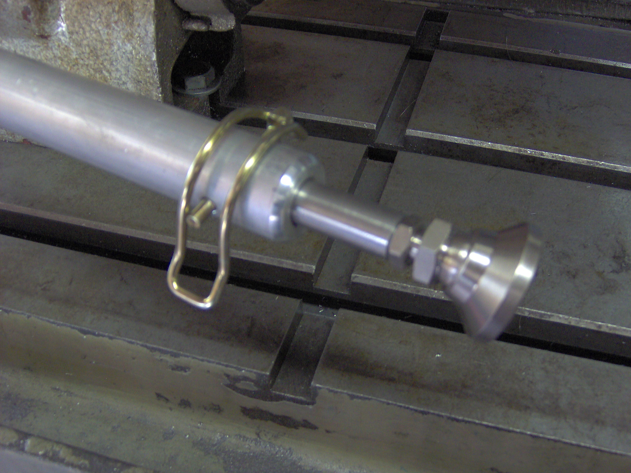
The mounting rails are connected with stainless steel spacer rods and flat head cap screws. Stainless steel pins are inserted through the front and rear mounting holes and secured with hitch pins. The mounting rails were sent to the customer at this point so that the camera could be attached and the pivot point located to aid in balancing the camera.
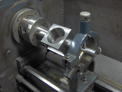
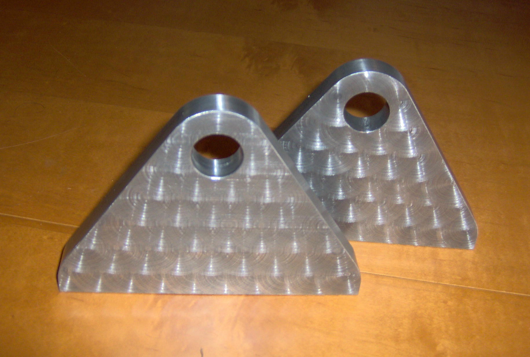
Below are the pivot brackets that will permit the up and down aiming of the camera. A swirl pattern was used to decorate the brackets.
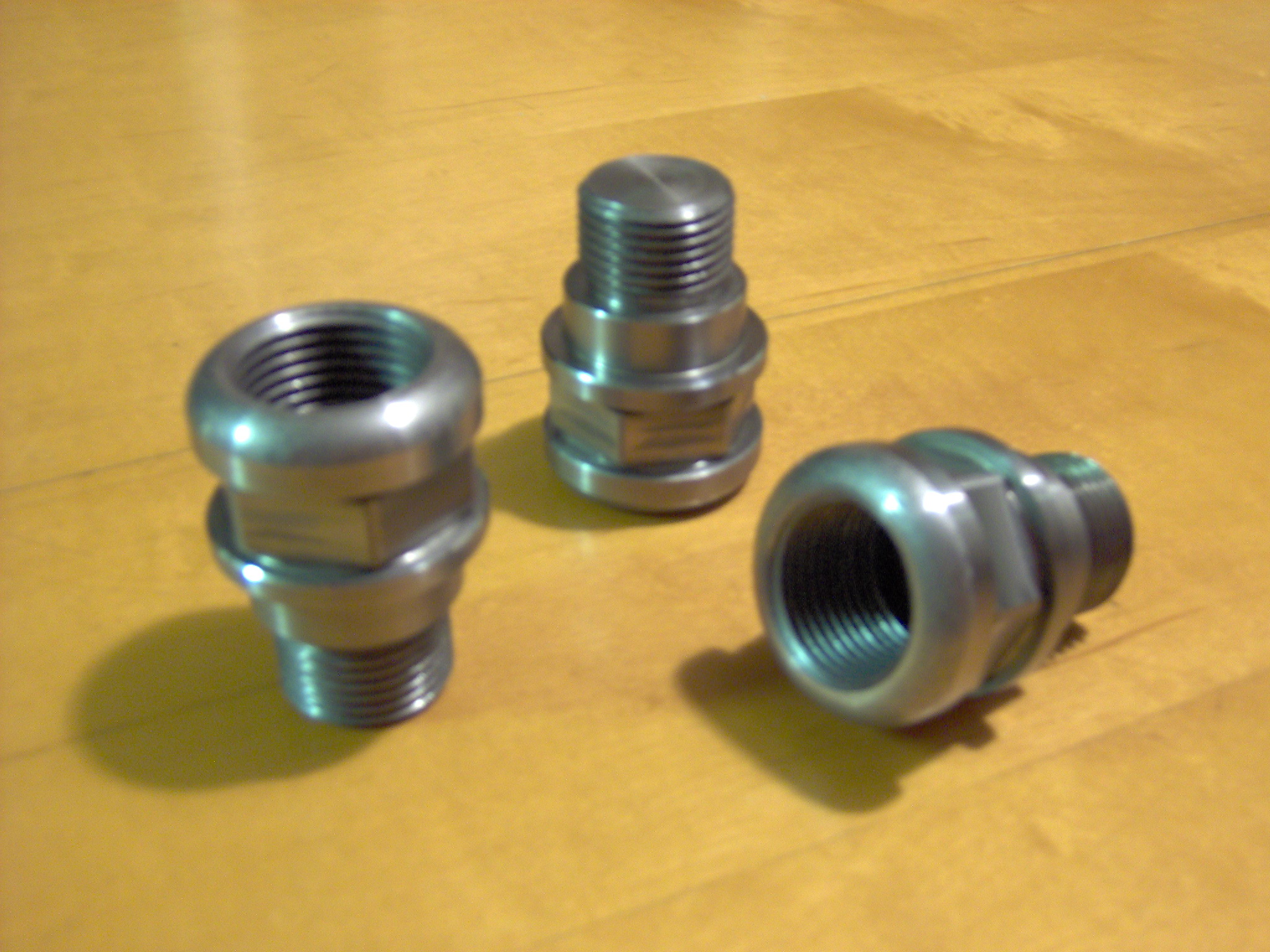
Stainless steel adapters were machined that will be inserted into the bottom of the tripod base plate. The adapters act as “stub legs” so that the camera can be mounted on the tripod base and displayed on a shelf.
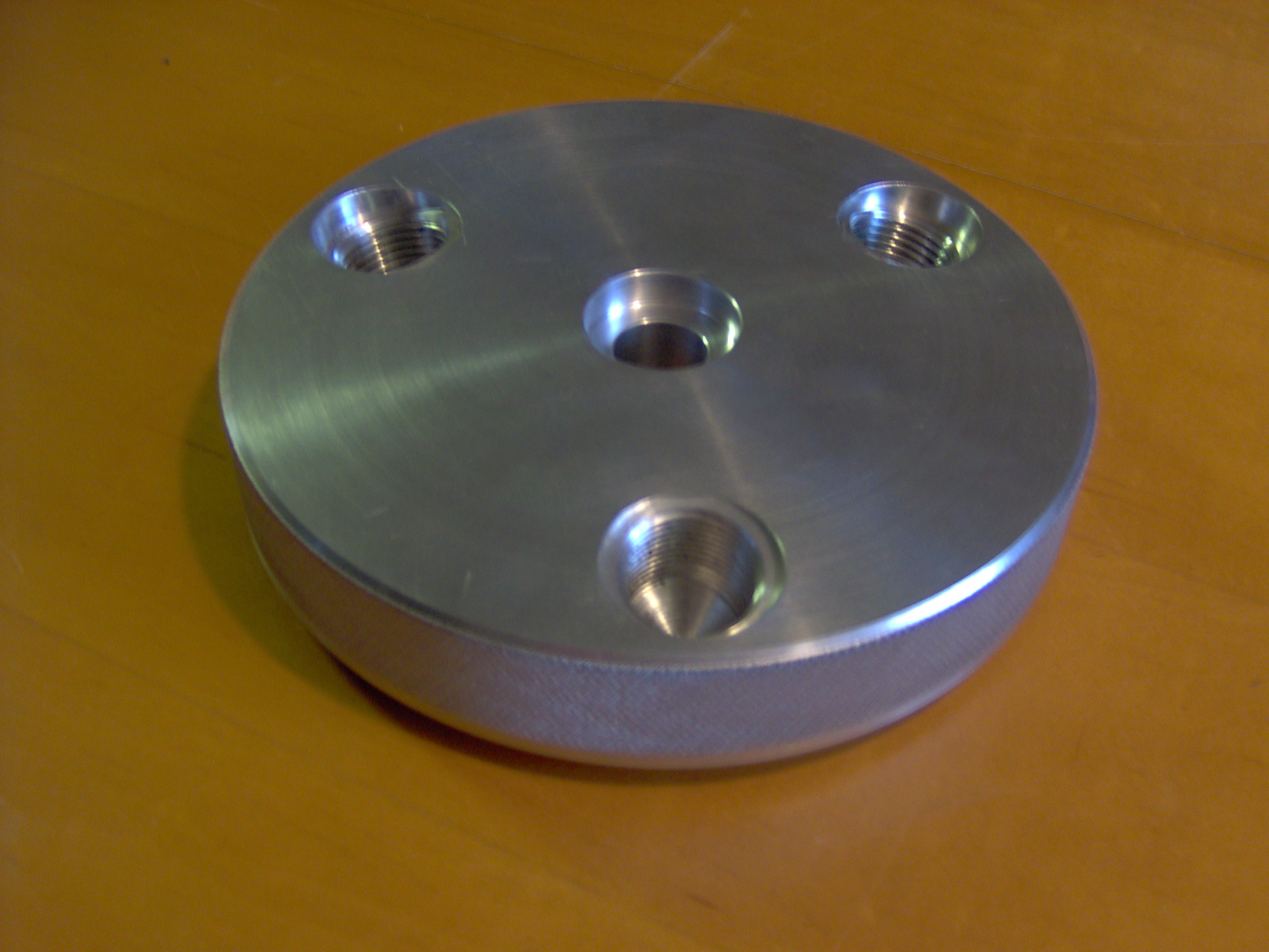
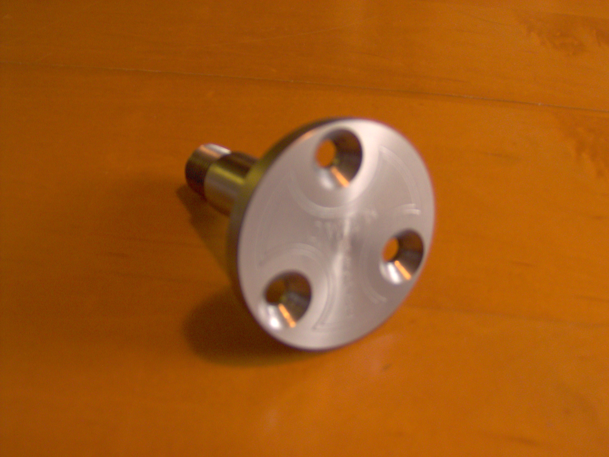
The next image is of the tripod mounting base. The threaded holes were machined at a 15 degree angle. The center bore and counterbores accept the spindle and thrust bearing assemblies.
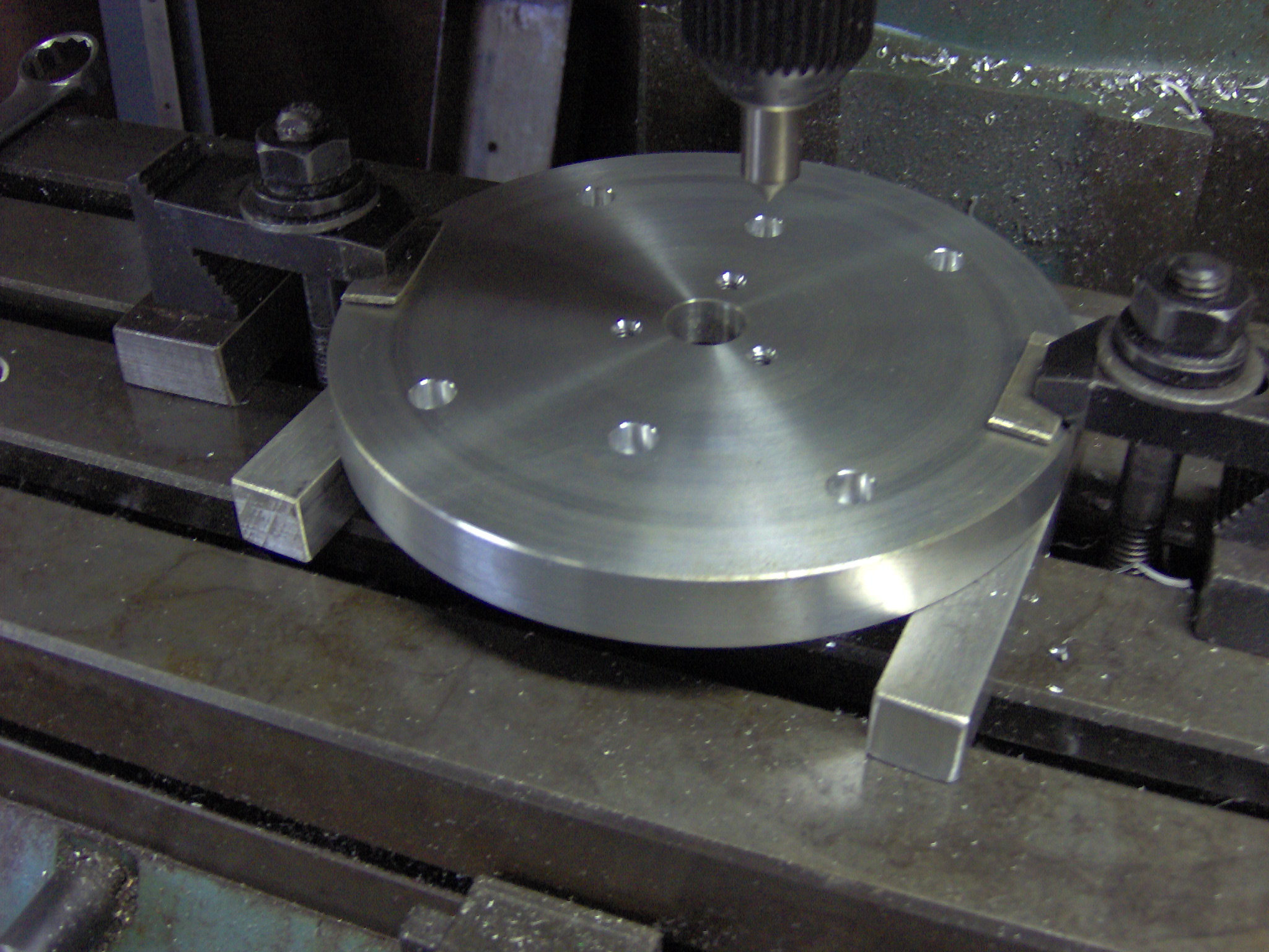
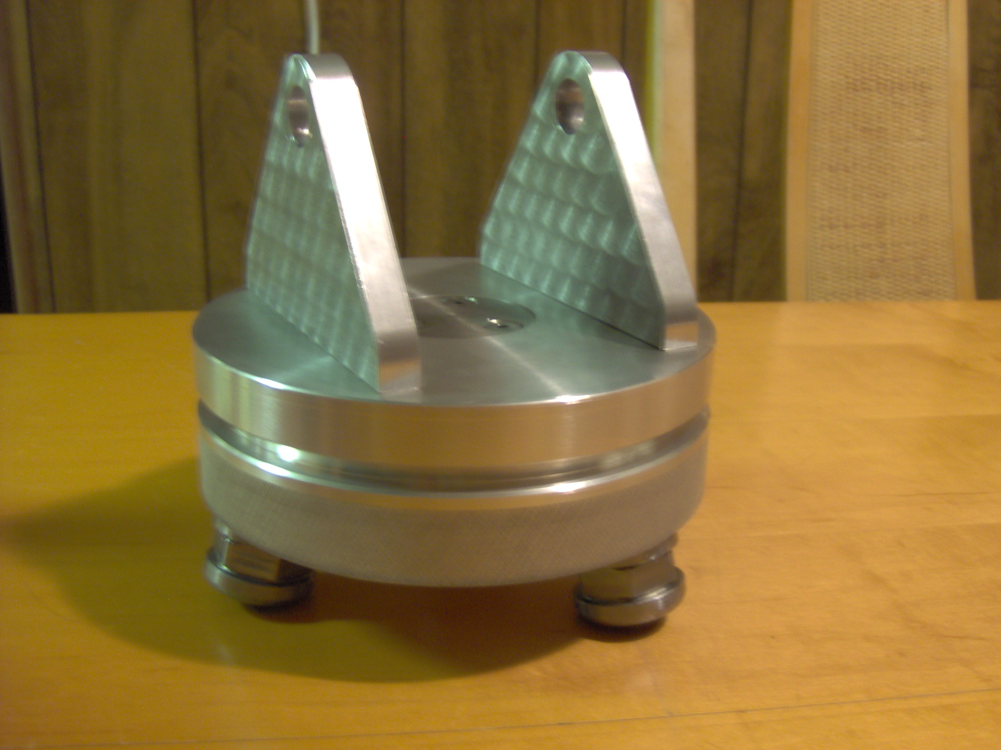
This is the underside of the rotating plate. The pivot brackets are each secured using 3 socket head cap screws.
This is the spindle that allows the top plate to swivel 360 degrees. The top of the spindle was engraved on the CNC mill, but the image is just to blurry to see the design clearly.
The assembled tripod body. A nylok nut was used to set the load on the spindle thrust bearings.
Leg extensions allow the tripod to be raised another 12 inches in one inch increments. Swivel pads were installed to allow precise leveling of the device.
Locking pins are used to retain the leg extensions inside the aluminum legs.
Another image of the assembled camera tripod.